We will use cookies on our website for technical, analytical, and marketing purposes. By continuing to browse this website, you agree to our use of cookies. To learn more, read our Privacy Policy.

Applications
World Leaders in Insulated Metal
Substrates and Circuits
Application 1
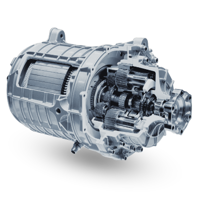
Powertrain
Thermal Clad materials are designed for high temperature solder and ENEPIG surface finish for eutectic AuSn die attach to reduce thermal resistance in Inverter
Thermal Properties
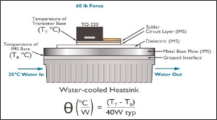
Thermal impedance is the property that matters most in determining the power density capability of the application. Lower thermal impedance results in lower junction temperatures. The lower the thermal impedance the more efficiently heat transfer from the component to the heatsink.
| Thermal Property | HPL | SJR | HT | MP | Test Method | ||
|---|---|---|---|---|---|---|---|
| Thickness | Unit | Value | Value | Value | Value | ||
|
Product Thermal Conductivity A |
W/m-k | 7.5 B | 3.7 C | 4.1 D | 2.4 E | TO-220 | |
|
Dielectric Thermal Conductivity |
W/m-k | 3.00 | 2.70 | 2.20 | 1.30 | ASTM D5470 | |
| Thermal Resistance | 1.5mil (38µm) | °C-in²/W | 0.02 | - | - | - | ASTM D5470 |
| 2mil (50µm) | 0.03 | - | - | - | |||
| 3mil (76µm) | - | - | 0.05 | 0.09 | |||
| 4mil (100µm) | - | 0.03 | - | - | |||
| 6mil (152µm) | 0.08 | - | 0.11 | - | |||
| Thermal Impedance | 1.5mil (38µm) | °C/W | 0.30 | - | - | - | TO-220 |
| 2.0mil (50µm) | 0.40 | - | - | - | |||
| 3.0mil (76µm) | - | - | 0.45 | 0.65 | |||
| 4.0mil (100µm) | - | 0.58 | - | - | |||
| 6mil (152µm) | 0.58 | - | 0.70 | - |
• The chart above represents some standard product offerings. There are new thicknesses and variants being developed.
Please inquire with your sales representative for more information
A Product thermal performance based on 1.6mm Al and 2oz copper. B Based on 1.5mil HPL. C Based on 4mil SJR. D Based on 3mil HT. E Based on 3mil MP.
Electrical Properties
Dielectric Breakdown Voltage
ASTM D149 definition of dielectric breakdown voltage is the potential difference at which dielectric failure occurs under prescribed conditions in an electrical insulating material located between two electrodes. This is a permanent breakdown and is not recoverable. Results obtained by this test should not be used to directly determine the dielectric behavior of a material in an actual application.
Note: Dielectric breakdown for PCB laminates is usually tested to IPC TM-650 test method 2.5.6 for breakdowns across the material and test method 2.5.6.2 for breakdown through the material; i.e., layer to layer.
| Electrical Property | HPL | SJR | HT | MP | Test Method | ||
|---|---|---|---|---|---|---|---|
| Thickness | Unit | Value | Value | Value | Value | ||
| Dielectric Breakdown Voltage |
1.5mil (38µm) | KVAC | 5.0 | - | - | - | ASTM D149 |
| 2.0mil (50µm) | 7.7 | - | - | - | |||
| 3.0mil (76µm) | - | - | 8.5 | 8.5 | |||
| 4.0mil (100µm) | - | 9.2 | - | - | |||
| 6mil (152µm) | 17.4 | - | 11.0 | - | |||
| 9mil (225µm) | - | - | 20.0 | - |
Mechanical Properties
Tg / CTE
Relative to traditional FR4 materials containing fiberglass, the z-axis expansion of Thermal Clad is considerably lower. This reduced z-axis expansion combined with the thin nature of the Thermal Clad dielectric layer results in significantly less stress on plated through holes (PTH).
| Mechanical Property | HPL | HT | MP | HR | FR-4 | Test Method | |
|---|---|---|---|---|---|---|---|
| Unit | Value | Value | Value | Value | Value | ||
| Glass Transition, Tg | °C | 185 | 150 | 90 | 90 | 170 | ASTM E1356 |
| CTE in XY/Z Axis , < Tg¹ | µm/m°C | 35 | 25 | 40 | 25 | 60 | ASTM D3386 |
| CTE in XY/Z Axis , > Tg² | µm/m°C | 85 | 95 | 110 | 95 | 250 | ASTM D3386 |
Technical Resources
-
#1HPL
Highest performance dielectric available if very thin, 38µm thickness for lower voltage applications, < 150 VDC, and up to 150µm for high voltage application <1200 VDC -
#2HT
Excellent thermal performance for single and two-layer applications -
#3MP
Standard thermal performance dielectric for lower operating temperature applications -
#4SJR
High thermal performance dielectric specifically designed to reduce fatigue stress caused from CTE mismatch between the aluminum base and the ceramic component
Downloads
-
THERMAL CLAD: TOOLS FOR THE OPTIMAL DESIGN
Circuit Design Guidelines -
IMS Material Selection Guidelines